Reverse Engineering
Delivering a True Time Savings: 3D Laser Scanning For Aviation
Have you ever stepped back at the end of a project and wondered if there would have been an easier way? Considering how much technology has advanced, in even in the last decade, it’s an easy question. It seems recently the challenge is figuring out which technology works the best or is the most applicable to one’s project.
AirCorps Aviation knew that applying 3D scanning to reverse engineering rare aircraft parts would save time in their restoration efforts, but with a variety of scanners on the market, which would work the best? Through research and testing, it was apparent that leaps in accuracy, speed and quality have made portable 3D laser scanning the most viable and best return on investment of time. Over a series of these blogs, we invite you to follow along and learn how 3D scanning has become an integral tool in the aviation industry for a variety of applications, especially for reverse engineering aircraft parts.
In this first post, we’ll break down the basics of portable 3D laser scanning, learn what it outputs and why that saves you time.
What is a portable 3D laser scanner?
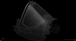
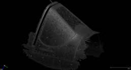
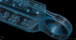
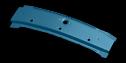
At it’s basic definition, a 3D scanner is a device that analyzes a real-world object to collect data based on its shape and possibly its appearance (e.g. color). This data instantly builds itself as a replication of the object in 3D in the form of millions of points or connected together appearing as triangle mesh. The collected data can then be used to construct a digital 3D model or take specific measurements at any given point, often referred to as metrology.
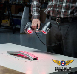
When 3D scanning comes to mind, images of cameras and units fastened to a tripod or arm traditionally appear. While these units still provide highly accurate data, it’s their portability and physical limitations that separate them from a portable 3D laser scanner. Within the last decade, huge leaps in accuracy, speed and quality have catapulted hand held scanners utilizing self-positioning technology to the top. It’s this portability that allows for flexibility in a myriad of scanning tasks inside or even outside of hangars. This portable 3D laser scanning is what AirCorps Aviation has invested in and has successfully been applying to a variety of aircraft projects.
What is the 3D scanning process?
The first step of the process in any potential 3D scanning project is having a conversation with an application engineer and determining if 3D scanning will provide benefit. Even with 3D scanning the old truism applies- just because you can, doesn’t always mean you should. If one determines that 3D scanning is applicable, the next step is to define what the deliverables are. Can you work with scan data reference alone? Can you build your own CAD model? Do you have the equipment to fabricate parts yourself once you have created a CAD model? Where will the scanning happen? Objects are usually scanned in 3D for two primary purposes: Reverse engineering and Inspections. They each have different workflow paths and along them you may be able to perform some of the work yourself. Whatever the case, these are just some of the questions that are necessary before starting actual scanning and are all ones that our application engineers can help you answer.
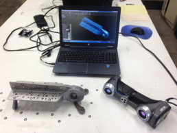
Once the project has been approved to proceed and it’s deliverables defined, self-positioning targets are applied to or around the object. These positioning targets are the breakthrough innovation that allows the object being scanned as the reference for positioning. If you have the opportunity to see the scanning in person you will probably be amazed just how fast the object is captured! This data is what provides the base or platform for what we refer to as reference.
What are the results?
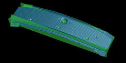
Most people who experience the instant results of 3D scanning are justifiably impressed. However, this process typically only represents only the first step in a reverse engineering project. Without a software to clean, repair, and produce usable reference that can be exported from the scan, it has little value. This next step of cleaning, repairing and generating reference is referred to as post-processing. This step is critical and not all scanners provide the software in order to perform this task. This post-processing software is the bridge to CAD (computer aided design). The post-processed model can be typically be exported as an STL (STereoLithography or Standard Tessellation Language) file or converted to Non-Uniform Rational B-Spline (NURBS). These files are what provide the platform and base for useful reference when starting in CAD and reverse engineering.
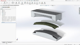
I often get the following question: “Why is it necessary to model the part in CAD since in theory I have just obtained a model by scanning it?” The answer is because the scanned model is not in a format that allows for editing or modifications to its properties. On the contrary, CAD models can produce a parametric solid body part that can be modified, edited and referenced for building additional tooling necessary to fabricate the duplicate part.
If you think about it, often the parts that are scanned are damaged and or only a portion of them is available to be scanned. If you replicated them in this state you would only be producing another damaged or incomplete part. Another common questions is – can I just 3D print the part? Answering this question usually requires more information. While it is true that a 3D scanned part can be post-processed and then 3D printed, it’s not likely that the part can be printed in a material that is serviceable. At least not cost-effectively. In addition, it goes back to the question – why would I want to print a damaged part? Remember, most of the time the goal of the reverse engineering workflow is to obtain a perfectly made duplicate part from the original specified material. It’s the CAD software that provides the platform to perform that critical task. The post-processed 3D scan reference is imported simply to aid in efficiency and accuracy of replicating that part.
Wrapping up
In conclusion, I hope that the process of 3D scanning does not sound too complex or daunting. Rather, that within this first post you gain insight on the basics of what a 3D scanner is, what steps are taken to produce data, and finally what you can expect it to generate. One important point to keep in mind with this technology is that it excels in capturing complex aircraft shapes, very accurately, and puts you into the fabrication stages at a much faster rate. In conjunction, those resulting fabricated parts have a much higher percentage to fit perfectly the first time. How many times have you seen reverse engineered parts not quite fit, only to start the measurement process over again. Not only is that money wasted on materials but have you added up the man hours spent measuring that part?
Still not quite sure how scanning can be applied to your aircraft? Hang in there, in future posts we will start to look at specific aircraft applications in detail and how 3D scanning benefited them. Hey, we’ll even look at a project that benefited from 3D scanning and printing!
If you can’t wait to see these applications, visit our reverse engineering page to learn more. Or, of course, contact us and we can discuss your applications in person.

